Back on the Air!
April 5, 2019
Greetings LaserSETI supporters. Many of you may have been wondering if the project was proceeding, but I write today to assure you it has and provide a comprehensive report on our progress these past 9 months since we last updated you. We apologize for the stall in our communications to you, and will definitely improve the pace of our reports to you as we drive forward to deployment on the sky!
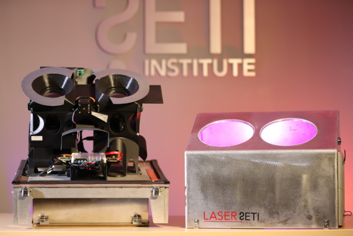
At the time of the last update, in June 2018, two LaserSETI cameras were mounted with their gratings, and lenses into 3-D printed mounts, and fabrication of their environmental, stainless steel enclosure was anticipated to start within the week in accordance with detailed CAD drawings. First light on the observing system of 2 enclosures (4 cameras) was estimated to be 4 months away.
So, here we are 10 months later, having worked through an intensive Devil-is-in-the-details epoch—and, where are we? Very close! The instruments are fully built and undergoing the last test required before going out under the sky.
Fabrication
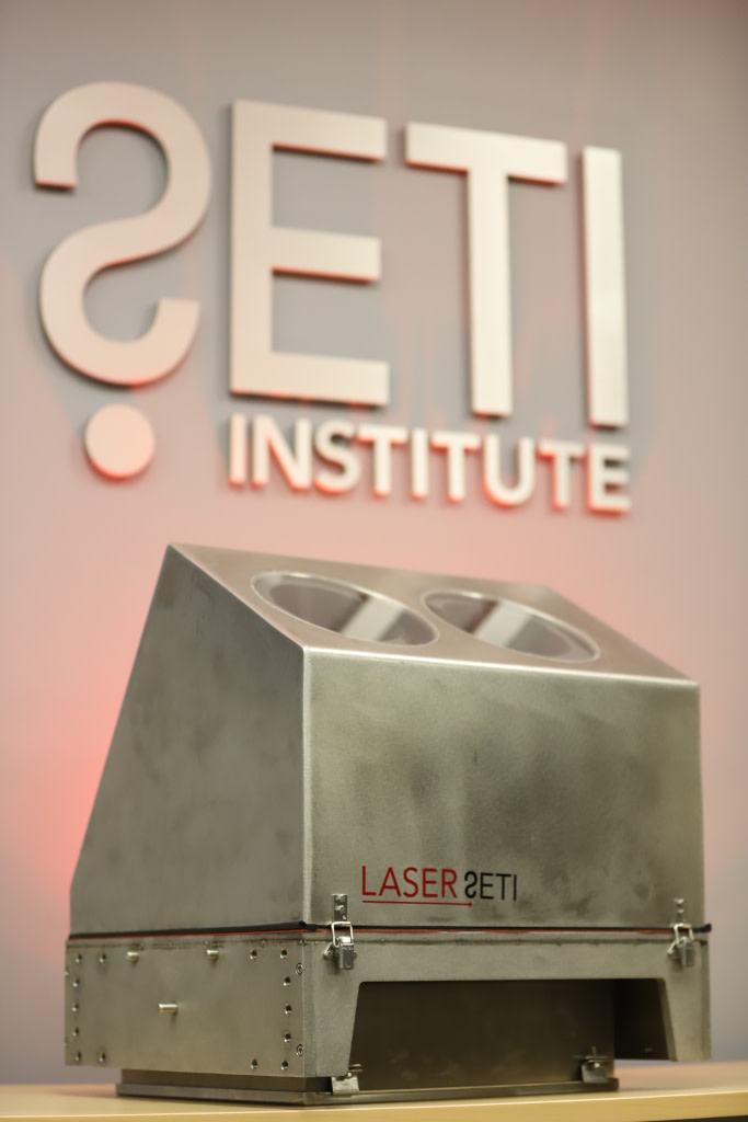
The CAD drawings for this component underwent several modification cycles to make sure the first two units manufactured would be as close as possible to the final configuration to be deployed globally. East Bay Machine and Sheet Metal in Concord CA was selected to do the precision component manufacturing because of their previous experience with astronomical observatories and their expertise in working stainless steel. Injury on their staff caused the delivery date to slip to late October.
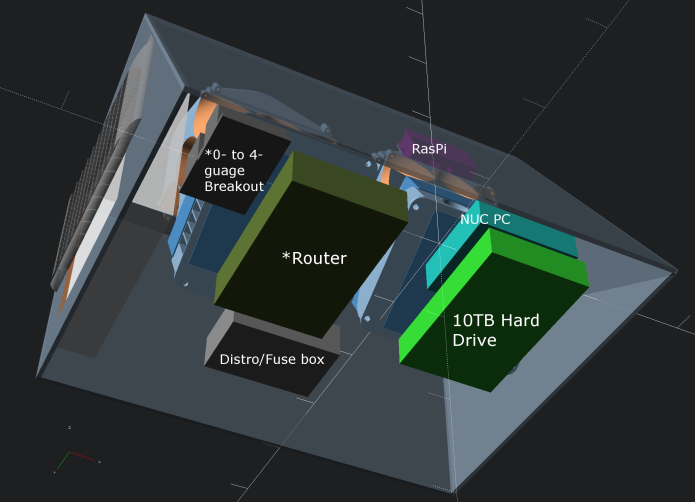
The delivered units, due to the difficulties in stainless steel welding, contained an unanticipated and uneven gap between the cover and base of the enclosure. This was eventually sealed with a combination of silicone rubber sheet and weather-resistant EPDM foam. Two 200 mm diameter, 6mm thick, optically flat Borofloat windows were sealed in place with E6800 industrial adhesive and tested by floating the cover upside-down as well as outside in winter rains, to validate all the waterproof seals. Cameras, gratings, motorized shutter windows, a Raspberry Pi 2b control computer with a GPS-based microsecond-accurate time server and environmental sensor suite, MERV13 air filter, Intel PCs for image processing, 10 TB hard disk for data archiving, and a 12VDC power distribution block with fuses were installed, wired, and tested inside the two enclosures. Care was taken with component placement and individual light baffles were implemented to ensure that no light from the various LEDs could enter the cameras.
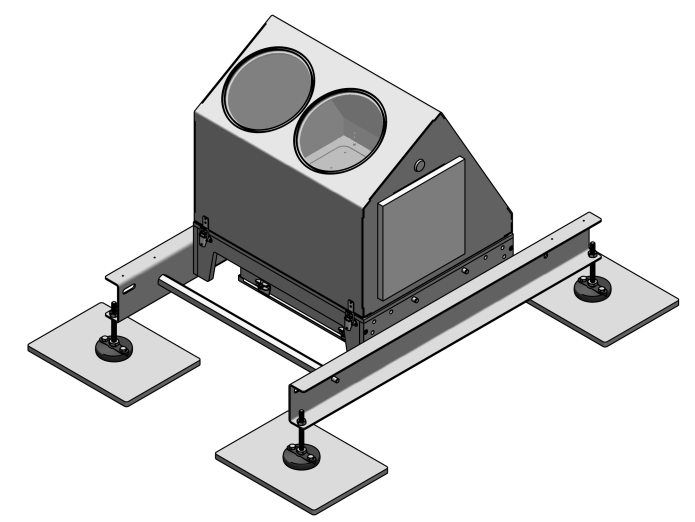
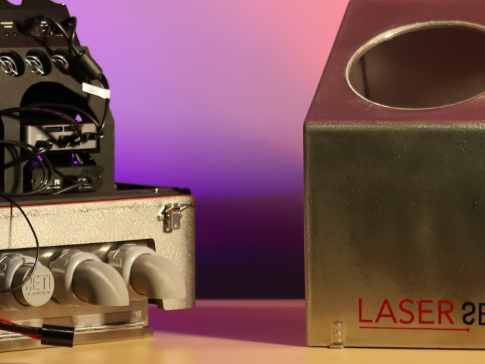
Once all the equipment was installed and the enclosure sealed, thermal testing began and identified an inadequacy in heat elimination: the camera-powered exhaust system, which had already been scaled back to support cover removal, wasn’t pushing heat efficiently enough out of the enclosure, causing the cameras to warm up. Several simple designs were tested, and the most effective design was an “active tailpipe,” shown below. A single high-quality computer fan sits behind these two downward-facing exhausts, forcing a strong outward airflow, through a stainless-steel mesh which protects against ingress of foreign objects, while the large area of the MERV13 filter lets in clean, cool air into the instrument bay. The system now keeps the camera bodies within 4C of internal ambient temperature which in turn is within 10C of external ambient—a good balance to keep warm in the winter and cool in the summer.
Site Deployment
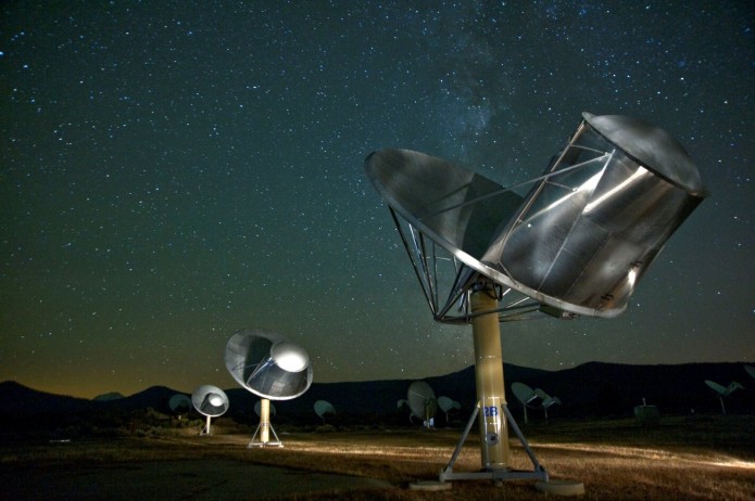
While our original plan was to partner with an optical observatory in California, we ultimately decided on the Hat Creek Radio Observatory—home of the SETI Institute’s Allen Telescope Array. Since LaserSETI’s unique imaging technique adds up light across its whole field of view, it was a better site because the lower light pollution levels mean more sensitivity to faint signals.
There are other synergies associated with this choice of a SETI-focused facility, but one obvious problem: this is a radio astronomy facility, and therefore particularly sensitive to RFI (radio frequency interference) potentially generated by the digital components of LaserSETI. As such, it is necessary to ensure that the additional electronics does not interfere with the sidelobes of the extremely sensitive telescopes. A test plan to evaluate LaserSETI against ITU Rec 279 has been developed and is to be executed soon. This is the last remaining test, necessarily coming after all other modifications to the instrument and enclosure.
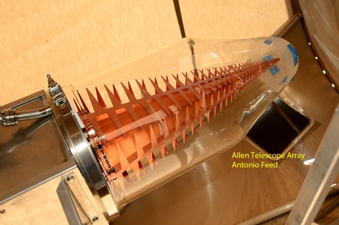
We will perform the tests in the shield room at Minex Engineering in Antioch, CA. We will use an ATA “feed” as the receiver and test at all frequencies from 1 to 10 GHz (the frequencies at which the ATA operates) using a spectrum analyzer programmed to step the receiver frequency band with 10 Hz spectral resolution, maximizing lab sensitivity to any squeak Laser SETI might emit. At this resolution, it takes just under 10 seconds for each 1 MHz of bandwidth tested, so something over a day for the full scan. We’re planning on a week to complete these tests. This is an unanticipated requirement, but one that makes a great deal of sense, both now for this first deployment but also future sites around the globe where the ideal site may again be a radio observatory.
Assuming no significant and difficult issues are found in the RFI testing, deployment is now projected for late April or early May. Then we begin the first operational phase: seeing every aspect of the carefully designed and tested system validated in the field—and gathering enough observational data to begin to analyze Laser SETI’s unique window on the universe!