PCBs: Progress and Compromise
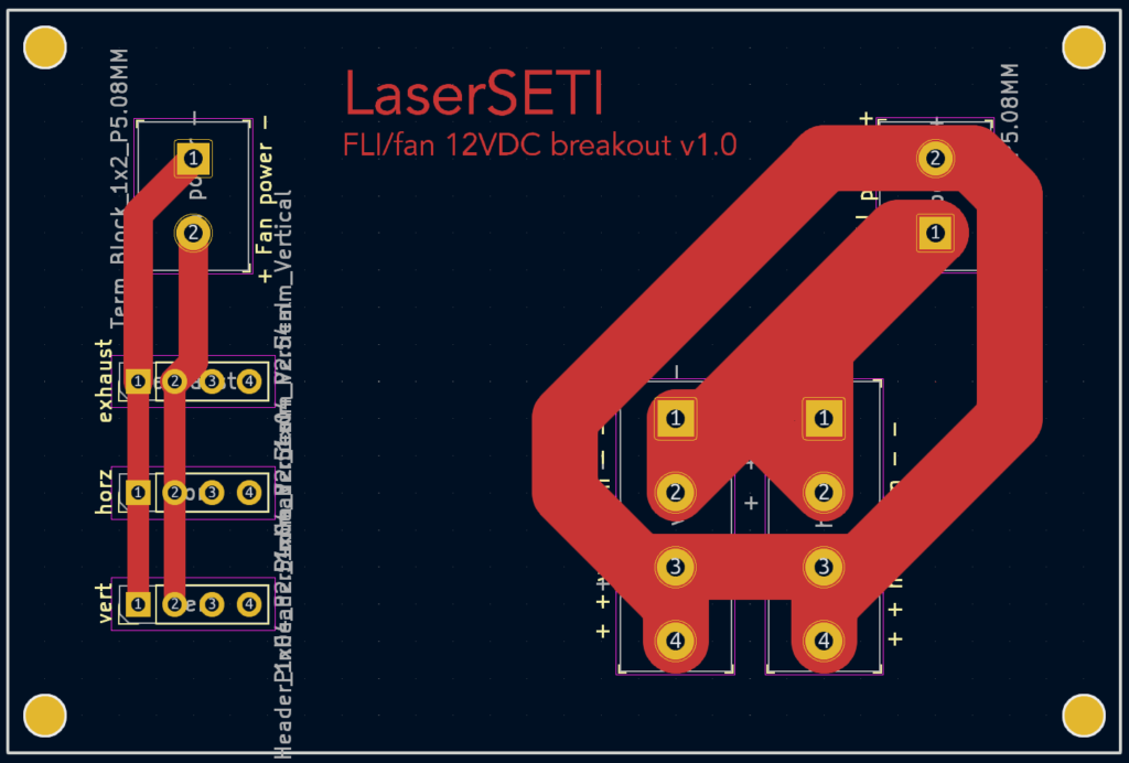
Making our next 10 instruments efficiently, as well as ensuring their reliability and ease of maintenance, is a top priority. Some of you might remember a previous iteration of a power board, an attempt to reduce wiring and build effort that encompassed all power wiring in the instrument and attempted to eliminate a COTS (commercial off the shelf) component. That board, however, was overpriced and unnecessarily aggressive, so we switched vendors, changed how we did the cabling to avoid joints, and reduced the scope of the board to handling the two remaining wiring challenges: the fans and FLI cameras.
The result is above and below, and is 40x cheaper than before, while still eliminating all of the manual labor, difficulty when swapping out components, and long-term reliability risk! Fans plug into 4-pin headers, and FLI cables will screw into block terminals (not rendered below) in the bottom right. No soldering, everything labelled, quicker and better than could be done by hand.

We hope you enjoy these peeks into the details behind LaserSETI, but stay tuned for some bigger updates and announcements soon!